

Change transformation settings
The Transform panel includes several options that determine how objects are transformed and how transformations are displayed in the Transform and Control panels.
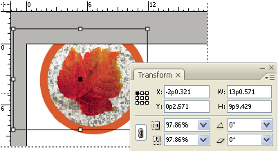
 Change the reference point for selected objects
All
transformations originate from a fixed point on or near the object,
called the reference point. The reference point is
marked by an icon  when
a transformation tool, such as the Scale tool, is active.
when
a transformation tool, such as the Scale tool, is active.
 Do one of the following:
-
To specify a different reference point for the selected object, click any of the nine points on the reference point locator
 in
the Transform or Control panel.
in
the Transform or Control panel.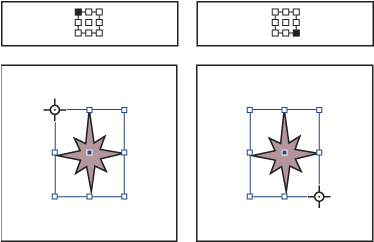 As you click different reference points on the Transform or Control panel (top left and right), the reference point for the selected object changes (bottom left and right).
-
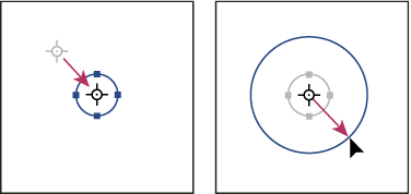
To move the selected object’s reference point to a specific location, select the Rotate tool
 , the
Scale tool
, the
Scale tool  , or
the Shear tool
, or
the Shear tool  , position
the tool over the reference point icon, and then drag it to a new
location. Or, with one of these tools selected, click anywhere on
the object or page. The reference point moves to that location.
, position
the tool over the reference point icon, and then drag it to a new
location. Or, with one of these tools selected, click anywhere on
the object or page. The reference point moves to that location.
The last-selected reference point on the reference point locator becomes the new default reference point for all tools and objects. If you drag an object’s reference point icon to a custom location (not on an anchor point), the panel reference point returns to the default position once the current object is no longer selected. InDesign preserves the default reference point position for new documents so you don’t have to reset it.
Change the information displayed for nested objects
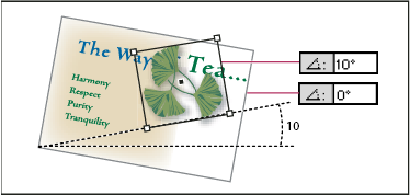
The Transform panel orients an object to a spread’s pasteboard, where a horizontal line has a rotation angle of 0°. By default, this is true even if the object is nested inside a transformed container object (that is, if the object is part of a transformed group or pasted inside a transformed frame). For example, if you paste an unrotated graphic inside a frame, rotate the frame 10° with the graphic inside, and then select the graphic using the Direct Selection tool, the Transform panel displays the graphic’s rotation angle as 10°.
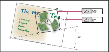
If you prefer, you can deselect the Transformations Are Totals command to see the same information relative to the nested object’s container. In the example above, if you deselect Transformations Are Totals, the Transform panel displays the graphic’s rotation angle as zero (the angle it has relative to its rotated container).
- Open the Transform panel or Control panel.
- In the Transform or Control panel menus, do one of the
following:
-
Leave Transformations Are Totals selected (the default) to display transformation values for nested objects relative to the pasteboard.
-
Deselect Transformations Are Totals to display rotate, scale, and shear values for nested objects relative to the container object.
-
Measure the position of selected objects
The Show Content Offset command determines
the appearance of the X and Y values in the Transform panel for
nested objects selected with the Direct Selection tool  . The
selected reference point in the reference point locator of the Transform
and Control panels determines which of the nine reference points on
the selected object is being compared to the zero point of the document
or to the zero point of a container frame. The zero point of a container
frame is always its upper left corner.
. The
selected reference point in the reference point locator of the Transform
and Control panels determines which of the nine reference points on
the selected object is being compared to the zero point of the document
or to the zero point of a container frame. The zero point of a container
frame is always its upper left corner.
The position of selected objects is measured from three positions:
-
The position of the container frame in relation to the zero point of the document. With Show Content Offset turned on or off, select the container frame using the Selection tool.
-
The position of the nested object in relation to the zero point of the document. Turn off Show Content Offset and select the nested object using the Direct Selection tool.
-
The position of the nested object in relation to the zero point (upper-left corner) of its container frame. Turn on Show Content Offset and select the nested object using the Direct Selection tool.


If Show Content Offset is selected, the X and Y values of the embedded object appear relative to the container object, and the X/Y icons in the Transform panel change to X+/Y+. If this command is deselected, the nested object values appear relative to the rulers.
In the Transform or Control panel menu, select
or deselect Show Content Offset.Include or exclude stroke weight in measurements
Stroke weight can affect an object’s size and position. You can change the stroke’s alignment and then choose whether the Transform panel measures an object’s size and position from the center or from the edge of its stroke. For information on changing stroke alignment, see Stroke panel options.
In the Transform or Control panel menu, do one
of the following:-
Select Dimensions Include Stroke Weight when you want panel measurements to represent the outer edge of an object’s stroke. For example, if one frame is 2 points shorter than the other, but the shorter frame’s stroke is 2 points thicker, this setting will cause both frames to display the same height values in the Transform and Control panels.
-
Deselect Dimensions Include Stroke Weight when you want the panel measurements to represent an object’s path or frame regardless of its stroke weight. For example, two frames of the same height will display the same height values in the Transform and Control panels, regardless of differences in their stroke weights.